
Cone Beam CT for Pre-Surgical Assessment of Implant Sites
David C. Hatcher, DDS, MSc. MRCD (c)
From the Summer 2005 AADMRT Newsletter  David C. Hatcher, DDS David C. Hatcher, DDS
ABSTRACT: The presurgical assessment of proposed implant sites requires very specific and accurate data. Imaging has always been used to assist with the implant site assessment but until the recent introduction of cone beam CT (CBCT) scanners the available imaging had a low value when considering the ratio between diagnostic potential, cost of study and risk to the patient. We are currently enjoying the 2nd and 3rd generation CBCT scanners. The use of CBCT scanners as maxillofacial imaging modalities have proven to be an extremely useful imaging tool for pre-surgical assessment of implant sites. CBCT scanners are easy to use and produce a 3-dimensional image volume that can be reformatted using software for customized visualization of the anatomy. Protocols have been developed that optimize the visualization of image for implant site assessment.
Anatomic and prosthetic factors are considered by the clinician to determine the best implant placement sites. Implants need to be placed where they have the best chance for success. The implant not only needs to be located in an area of a missing tooth but the implant needs to be placed in a way to satisfy restorative, esthetic, biomechanical and functional requirements (prosthetic considerations). Imaging can be used to determine status of the anatomy in the proposed implant site and how to best optimize the implant placement considering the prosthetic needs and anatomic constraints. An imaging stent can be used to provide detailed feedback relating the prosthetic and anatomic considerations. Determining the relationships between the anatomic and prosthetic considerations leads to the development of a set of imaging goals and the methods required for achieving the desired imaging outcome. Ideal imaging studies are the successful fulfillment of goals derived to solve specific clinical problems. There is a wide spectrum of imaging options requiring a thoughtful strategy to select imaging techniques that produce optimum diagnostic information. The ideal imaging modality produces the desired diagnostic information while minimizing the cost and risk to the patient.
The purpose of this article is to introduce volumetric imaging (cone beam CT) for pre-surgical assessment of implant placement and to compare this technique with other available imaging techniques. |


|
IMAGING GOALS:
GENERAL IMAGING GOALS: Once the implant sites have been determined then the imaging strategies and goals can be developed. In all cases the replacement of the missing teeth involves restoring a portion or all of the occlusion and therefore there may be anatomic interests that extend beyond the implant site. This may be an important consideration when determining the imaging strategy. For example, do you want the region of interest extended beyond the implant site to include all components of the articulation, such as the opposing arch, maxillomandibular spatial relationships and temporomandibular joints (TMJs). Imaging can be used by the clinician to understand the anatomic foundation for placing the implant and restoring the occlusion.
For each implant site the following anatomic considerations may allow the clinician to determine the best site for the implant and meet the prosthetic goals
Bone Quality: Dynamic loading of an implant imparts forces to the adjacent bone. There is an assumption that bone density is directly proportional to load bearing capacity of the bone and that implant failure is associated with low bone density8. The architecture of the supporting bone is also a factor associated with the functional capacity of these tissues. Dynamic loads received by the implants may strain the supporting bone and induce changes in that bone. Bone requires a certain amount of strain for maintenance, but excessive strain may cause fatigue failure of the trabeculae.
Long axis of the alveolar bone: Axis orientation describes the angle formed by the vertical long axis of the alveolar-basal bone complex when viewed in cross-section. Information about the axis orientation is important for successful alignment of the implant within the boundaries of the jaws. Determining the long axis of the alveolar bone allows the clinician to optimize the trajectory of implant placement with the emergence profile and loading characteristics of the implant (figures 1,3,4 ).
GENERAL IMAGING GOALS: Once the implant sites have been determined then the imaging strategies and goals can be developed. In all cases the replacement of the missing teeth involves restoring a portion or all of the occlusion and therefore there may be anatomic interests that extend beyond the implant site. This may be an important consideration when determining the imaging strategy. For example, do you want the region of interest extended beyond the implant site to include all components of the articulation, such as the opposing arch, maxillomandibular spatial relationships and temporomandibular joints (TMJs). Imaging can be used by the clinician to understand the anatomic foundation for placing the implant and restoring the occlusion.
- Image the entire region of interest (ROI)
- View the ROI in at least 2 planes at right angles to each other (3D perspective)
- Obtain images with maximum detail, minimal distortion and minimal superimposition
- The diagnostic value of the imaging study must in balance with the cost and risk associated with obtaining the study.
For each implant site the following anatomic considerations may allow the clinician to determine the best site for the implant and meet the prosthetic goals
- Determine bone height and width (bone dimensions).
- Determine bone quality
- Determine long axis of alveolar bone
- Identify and localize internal anatomy
- Determine jaw boundaries
- Pathology detection
- Transfer of radiographic information
Bone Quality: Dynamic loading of an implant imparts forces to the adjacent bone. There is an assumption that bone density is directly proportional to load bearing capacity of the bone and that implant failure is associated with low bone density8. The architecture of the supporting bone is also a factor associated with the functional capacity of these tissues. Dynamic loads received by the implants may strain the supporting bone and induce changes in that bone. Bone requires a certain amount of strain for maintenance, but excessive strain may cause fatigue failure of the trabeculae.
Long axis of the alveolar bone: Axis orientation describes the angle formed by the vertical long axis of the alveolar-basal bone complex when viewed in cross-section. Information about the axis orientation is important for successful alignment of the implant within the boundaries of the jaws. Determining the long axis of the alveolar bone allows the clinician to optimize the trajectory of implant placement with the emergence profile and loading characteristics of the implant (figures 1,3,4 ).
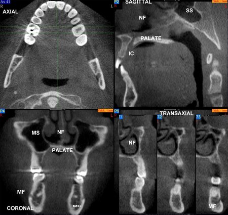
Figure 1: An image volume can be reformatted and displayed in multiple planes using software tools. The patient’s anatomy has been reformatted in axial (upper left), sagittal (upper right), coronal (lower left) and transaxial planes (lower right). Selected anatomy has been labeled as follows: Maxillary Sinus (MS), Nasal Fossa (NF), Mental Foramen (MF), Mandibular Canal (MC), Sphenoid Sinus (SS), Incisive Canal (IC) and Hard Palate (HP).
Internal anatomy: The most common internal anatomy to be identified and localized includes the mandibular canal, maxillary sinus, nasal fossa, mental foramen, incisive canal and adjacent teeth. Identifying these structures aid the clinician in determining the boundaries for implant placement (Figures 1,2,4).
Internal anatomy: The most common internal anatomy to be identified and localized includes the mandibular canal, maxillary sinus, nasal fossa, mental foramen, incisive canal and adjacent teeth. Identifying these structures aid the clinician in determining the boundaries for implant placement (Figures 1,2,4).
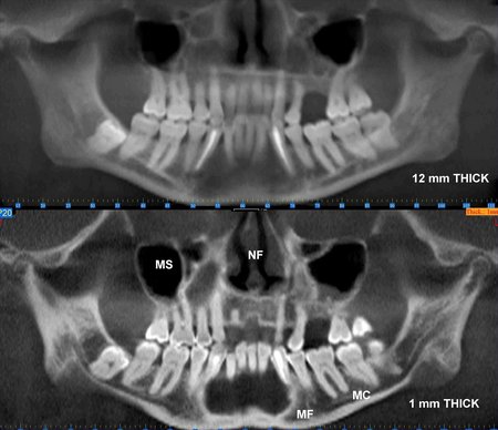
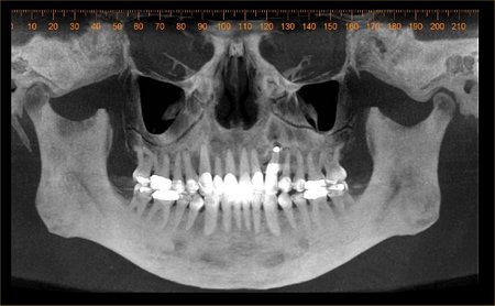
Figure 2:The maxillofacial structures have been reformatted and displayed in curved planes of variable thickness resembling a panoramic view. The upper image is 12 mm thick (buccolingual) and the lower image is 1 mm thick. Selected anatomy has been labeled as follows: Maxillary Sinus (MS), Nasal Fossa (NF), Mental Foramen (MF) and Mandibular Canal (MC). The reconstructed panoramic projection, Figure 2B, is being displayed using a maximum intensity projection (MIP) to optimize visualization of the teeth and bone.
Jaw Boundaries: Imaging can be used to identify the outer boundary of the jaws including impressions into the jaws, such as, fossae (Figure 1,3,4)
Jaw Boundaries: Imaging can be used to identify the outer boundary of the jaws including impressions into the jaws, such as, fossae (Figure 1,3,4)
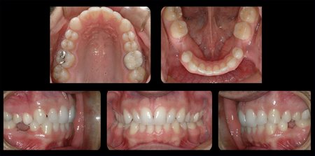
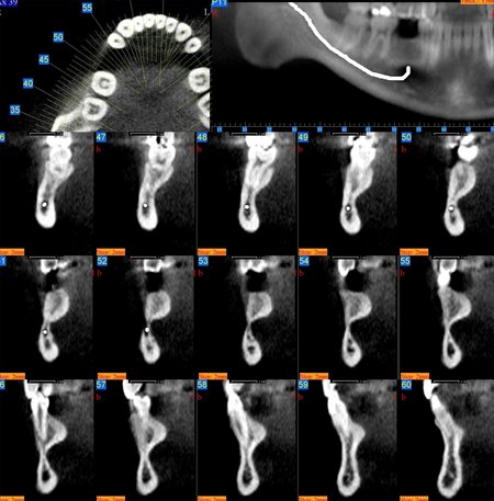
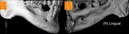
Figure 3: These images are for a 25 year old male with congenitally missing mandibular bicuspid teeth. The sites are being evaluated for feasibility of implant placement. The clinical photographs show the edentulous sites and suggest the presence of adequate vertical and buccolingual alveolar bone volume to place implants. The CBCT scan reconstructed in 3D, axially and transaxially showed a large lingual concavity that would severely limit implant placement
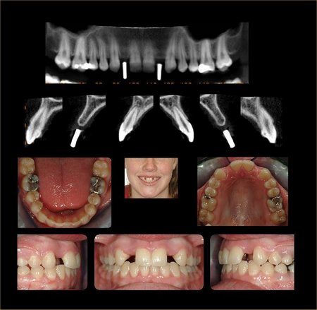
Figure 4: These images are for a 17 year old female with congenitally missing maxillary lateral incisor teeth. The sites are being evaluated for feasibility of implant placement with the aid of a radiographic stent. The clinical photographs show the edentulous sites and the CBCT scans show metallic stent markers. The stent markers have been placed simulate the proposed drill path that was determined by clinical exam. The CBCT images can be used to determine if proposed drill path (implant trajectory) will conform to the jaw boundaries.
Pathology detection: Jaw pathology in the proposed implant site or within the maxillofacial regions is important to detect, diagnose, treatment plan and treatment sequence. Abnormalities involving the alveolar ridge include retained root tips, inflammatory processes, cyst and tumors. In addition, anomalies involving other maxillofacial structures, such as, maxillary sinuses and temporomandibular joints (TMJs) may complicate the successful implant process. For example, changes in stress (force/area) directed at poorly adapted TMJs may increase TMJ symptoms. Changes in TMJ stress levels may result from operative manipulations, changes in masticatory abilities and changes in vertical dimension or maxillomandibular spatial relationships (Figure 5,7).
Pathology detection: Jaw pathology in the proposed implant site or within the maxillofacial regions is important to detect, diagnose, treatment plan and treatment sequence. Abnormalities involving the alveolar ridge include retained root tips, inflammatory processes, cyst and tumors. In addition, anomalies involving other maxillofacial structures, such as, maxillary sinuses and temporomandibular joints (TMJs) may complicate the successful implant process. For example, changes in stress (force/area) directed at poorly adapted TMJs may increase TMJ symptoms. Changes in TMJ stress levels may result from operative manipulations, changes in masticatory abilities and changes in vertical dimension or maxillomandibular spatial relationships (Figure 5,7).
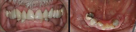
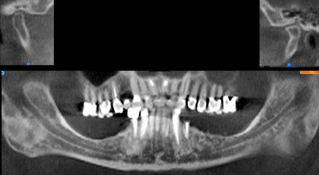
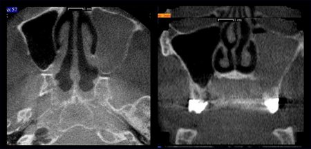
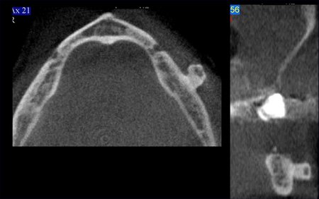
Figure 5: This sequence of images was prepared for a 64 year old male in the planning phase for mandibular posterior implants. A single CBCT scan created the opportunity to evaluate the proposed implant sites and the remainder of the maxillofacial region. In this case the following relevant information was acquired from the CBCT: left side maxillary sinusitis with an occluded osteomeatal complex, benign tumor (osteoma) extending from the buccal surface of the left side of the mandible, degenerative joint disease involving the left TMJ, over-eruption of the maxillary posterior teeth and the maxillomandibular spatial relationships.
Transfer of Radiographic information (communication): The diagnostic and treatment planning information gained during image analysis may need to be transferred. For example, the restorative dentist may perform the original image analysis and has made decisions about the precise placement location for implants and now wants to convey the information to a surgeon and/or patient. Images and derivative information can be used for downstream communication and knowledge transfer (Figure 6).
Transfer of Radiographic information (communication): The diagnostic and treatment planning information gained during image analysis may need to be transferred. For example, the restorative dentist may perform the original image analysis and has made decisions about the precise placement location for implants and now wants to convey the information to a surgeon and/or patient. Images and derivative information can be used for downstream communication and knowledge transfer (Figure 6).
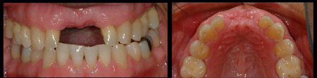
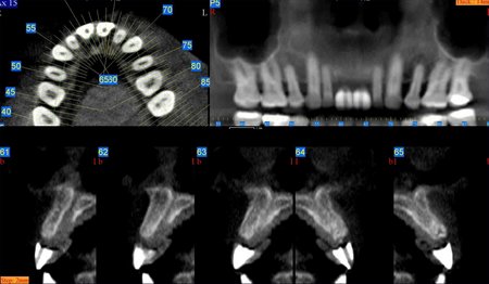
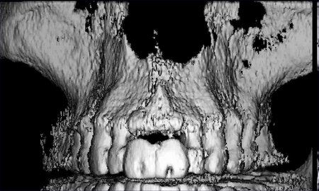
Figure 6: A 56 year old male missing teeth #s 8 and 9 had a CBCT scan with a radiographic stent in place. Opaque teeth were fabricated and positioned to simulate their desired final size and position. A hole drilled down the long axis of the teeth identifies the trajectory of the implant placement and to serve as surgical guides. The stent can be used as a reference for radiographic planning and to transfer the simulation product to the mouth.
IMAGING OPTIONS:
Several imaging modalities have been used for the pre-surgical evaluation of implant sites. Table 1 is a comparison matrix showing the relative value of the commonly available 2 and 3 dimensional imaging modalities1-15. The panoramic, periapical and cephalometric images contain superimpositions, have large information voids related to depth and are affected by projection geometry so that measurements are not reliable. Only tomography, conventional CT scans and cone beam CT scans provide the information desired about each implant site. When the imaging goals are extended to occlusion, maxillomandibular spatial relationships and the temporomandibular joint then cone beam CT scans stands alone as the best value.
VOLUMETRIC IMAGING:
Volumetric imaging (VI) or cone beam CT (CBCT)) creates the opportunity to extend the information yield beyond the conventional imaging methods and is an ideal modality for implant planning. CBCT produces accurate 3 dimensional image data. The field of view is scalable and one scan can include the entire maxillofacial region including the maxilla, mandible, base of skull and TMJs. Currently there are four CBCT units available in United States. The units have a voxel size that range from 0.1 to 0.4 mm3 and with a 12 bit dynamic range (4096 shades of gray). The small voxel size would allow feature detection size and dimensional accuracy in the range of 0.2-0.8 mm. A single cone beam CT scan contains enough information to satisfy the imaging objectives stated above including maxillomandibular spatial relationships.
Software is used to display and visualize the anatomy in a way that is clinically meaningful. The software allows for multiplanar reformation and display. The primary reconstruction of the raw data is completed parallel to the occlusal plane and therefore the occlusal plane is used as the visualization reference plane. The reconstructions can occur in the axial, coronal, sagittal, curved and oblique planes (Figures 1,2,4). The location, dimensions and thickness of the reconstructions can be varied to achieve the desired results (Figure 2). The manufacturers of CBCT scanners offer software that is capable of multiplaner reformations but third party software is also available to import and manipulate image data that has been exported in a DICOM format. Third party software includes Materialise Simplant, I Dent, and Nemotec Dental Systems.
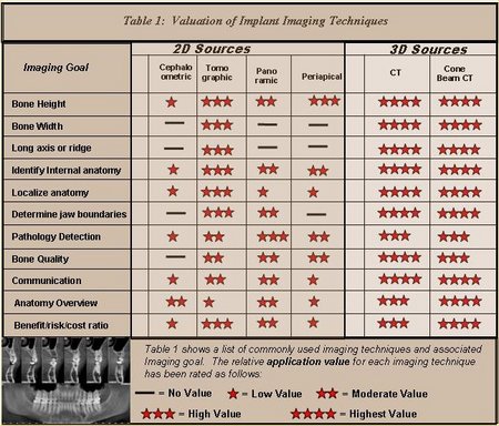
Table 1: This is a matrix showing the relative value various maxillofacial imaging modalities for the stated implant imaging goals.
SUMMARY:
CBCT, a maxillofacial imaging modality, creates the opportunity to provide the clinician with valuable information that improves the entire process of replacing missing teeth with implants. CBCT provides high quality of diagnostic images that have an absorbed dose that is comparable to other dental surveys and less than a conventional CT16. The large field of view and 3 dimensional image set offered by CBCT allows the clinician to adequately assess the implant site, look at the opposing occlusion, TMJs and other factors that may associated with the total success of implant based rehabilitation of the patient’s occlusion (Figures 5,7). Software and technology development trends suggest that in the near future CBCT scans will be used to develop a patient specific 3D model that will be used for implant diagnosis, treatment planning, treatment simulation, implant placement (surgery) and tooth replacement (restoration of implant).
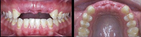
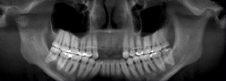
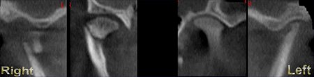
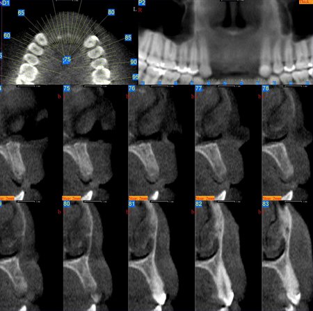
Figure 7: This series of images belong to a 19 year female that traumatically lost teeth #s 7-10. A typical implant work up would be isolated to the implant site (axial, transaxial, panoramic views) and allow for determination of the bone height, width and quality. With CBCT there is more information available, including the opposing occlusion and the TMJs. Evaluation of the TMJs showed left side degenerative joint disease and a right side sub-condylar fracture dislocation.
References
- Schropp L, Wenzel A, Kostopoulos L, Impact of Conventional Tomography on Prediction of the Appropriate Implant Size, Oral Surg Oral Med Oral Pathol Oral Radiol Endod 92:458-463, 2001.
- Yikontiola L, Moberg K, Huumonen S, et al, Comparison of Three Radiographic Methods Used to Locate the mandibular Canal In the Buccolingual Direction Before Bilateral Sagittal Splint Osteotomy, Oral Surg Oral Med Oral Pathol Oral Radiol Endod 93:736-742, 2002.
- Robinson S, Czerny C, Gahleitner A, et al, Dental CT Evaluation of Mandibular First Premolar Root Configurations and Canal Variations, Oral Surg Oral Med Oral Pathol Oral Radiol Endod 93:328-332, 2002.
- Pawelzik J, Cohnen M, Willers R, et al, A Comparison of Conventional Panoramic Radiographs With Volumetric Computed Tomography Images in the Preoperative Assessment of Impacted Mandibular Third Molars, J Oral Maxillofac Surg 60:979-984, 2002.
- Gaggl A, Schultes G, Karcher H, Navigational Precision of Drilling Tools Preventiing Damage to the Mandibular Canal, J Craniomaxillofac Surg 29:271-275, 2001.
- Siebegger M, Schneider BT, Mischkowski RA, et al, Use of an Image-Guided Navigation Sytem in Dental Implant Surgery in Anatomically Complex Operation Sites, J Craniomaxillofac Surg 29:276-281, 2001.
- Dula K, Mini R, van der Stelt PF, et al The Radiographic Assessment of Implant Patients: Decision-making Criteria, Int J Oral Maxillofac Implants 16:80-89, 2001.
- Norton MR, Gamble C, Bone Classification: An Objective Scale of Bone Dentisty Using the Computerized Tomography Scan, Clin Oral Implant Res, 12:79-84-2001.
- Cavalcanti MGP, Ruprecht A, Bonomie JM, et al, The Validation of 3D Spiral CT-Based Measurements of Simulated Maxillofacial Neoplasms, Oral Surg Oral Med Oral Pathol Oral Radiol Endod 89:753-758, 2000.
- Kaeppler G, New Radiographic Programs for Transverse Conventional Tomograms in the Dentomaxillofacial Region, Quintessence Int 30:541-549, 1999.
- Yang J, Cavalcanti MGP, Ruprecht A, et al, 2-D and 3-D Reconstructions of Spiral Computed Tomography in Localization of the Inferior Alveolar Canal for Dental Implants, Oral Surg Oral Med Oral Pathol Oral Radiol Endod 87:369-374, 1999.
- Almog DM, Torrado E, Meitner SW, Fabrication of Imaging and Surgical Guides for Dental Implants, J Prosthet Dent 85:504-508, 2001.
- Hashimoto K, Yoshinori A, Kazui I, et al, A comparison of a new limited cone beam computed tomography machine for dental use with a multidetector row helical CT machine, Oral Surg Oral Med Oral Pathol Oral Radiol Endod 95:371-377, 2003.
- Dixon D, Morgan R, Hollender L, et al, Clinical Application of Spiral Tomography in Anterior Implant Placement: Case Report, 73:1202-1209, Oct 2002.
- Hatcher D, Diagnostic Imaging, Reconstructive Preprosthetic and Maxillofacial Surgery, 2nd Ed. eds: Foseca R and Davis H, W.B. Saunders Company 1995
- Mah J, Danforth RA et al, Radiation absorbed in maxillofacial imaging with a new dental CT. Oral Surg Oral Med Oral Pathol Oral Radiol Endod. in Press.
David C. Hatcher, DDS, MSc, MRCD (c )
Diagnostic Digital Imaging
1 Scripps Drive, Suite 101
Sacramento, CA 95825