Physics Based Artifacts
Noise
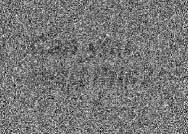
Noise is defined as an unwanted, randomly and/or non-randomly distributed disturbance of a signal that tends to obscure the signal's information content from the observer. Noise affects images produced by cone beam CT units by reducing low contrast resolution, making it difficult to differentiate low density tissues thereby reducing the ability to segment effectively.
The noise in traditional projection radiography is primarily from quantum mottle which is defined as a variation in image density due to statistical fluctuation of photon fluency in the radiation field. In well-designed x-ray systems, the quantum noise is governed by the number of x-ray photons absorbed in the detector, the higher the number of photons absorbed, the lower the quantum mottle. The number of x-ray photons emitted is directly related to the mA of the x-ray unit. Another source of noise in computed tomography is scattered radiation. Scattered radiation arises from interactions of the primary radiation beam with the atoms in the object being imaged and its magnitude is largely dependent on patient size, shape, and position in the scan field. It is a major source of image degradation in x-ray imaging techniques. When x-ray radiation passes through a patient, three types of interactions can occur, including coherent scattering, photoelectric absorption and Compton scattering. Compton scattering is the type most seen in diagnostic radiology. In Compton scattering, the interaction is a collision between a high energy x-ray photon and one of the outer shell electrons of an atom. This outer shell electron is bound with very little energy to the atom so when the x-ray photon collides with it, the electron is ejected from the atom. Because energy and momentum are both conserved in this collision, the energy and direction of the scattered x-ray photon depend on the energy transferred to the electron. If the initial x-ray energy is high, the relative amount of energy lost is small, and the scattering angle is small relative to the initial direction. If the initial x-ray energy is small, the scatter angle is large and the ejected electron disperses in all directions.
There is very little noise in conventional CT machines because of the high mA used and due to effective pre- and postpatient collimation which reduces the scattered radiation to a negligible amount. However, in CBCT machines the noise is high due to the lower mA used and because of the high amount of scattered radiation since there is no post-patient collimation.
An x-ray beam in medical radiography machines are composed of many x-rays with a wide spectrum of energies. Since all substances attenuate low-energy x-rays more strongly than high energy ones, primarily because of photoelectric absorption, a heterogeneous beam traversing an absorbing medium becomes proportionately richer in high-energy photons, and hence more penetrating, or 'harder'. Beam hardening manifests as two different artifacts within the reconstructed image, a cupping artifact and the appearance of dark bands or streaks.
Cupping artifacts from beam hardening occur when x-rays passing through the center of a large object become harder than those passing through the edges of the object due to the greater amount of material the beam has to penetrate. Because the beam becomes harder in the center of the object, the resultant profile of the linear attenuation coefficients appears as a "cup".
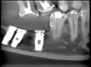
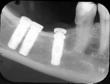
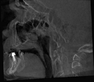
The second type of artifact relating to beam hardening are dark streaks and bands between dense objects in an image. In dental imaging, this type of artifact can be seen between two implants located in the same jaw that are in close proximity to each other. This occurs because the portion of the beam that passes through both objects at certain tube positions becomes harder than when it passes through only one of the objects at other tube positions.
Partial Volume Artifacts
The algorithms used in CT data reconstruction assume that the object is completely covered by the detector at all view angles, and that the attenuation is caused by the object only. When this situation does not occur, reconstructed CT images can contain a truncated-view artifact. In conventional CT units, this is not a problem as the entire object is always within the field of view of the unit, however it does affect CBCT units due to their limited FOV. This occurs because some of the cone beam data penetrating portions of the object other than the region-of-interest (ROI) are missing because of the insufficient size of the detector.
When the entire volume is not covered by the detector, shading artifacts can be visualized. Another consequence of the partial volume artifact is that the true linear attenuation coefficients cannot be calculated because some of the x-ray paths penetrate other portions of the object as well as the region of interest and the data collected no longer represent this area exclusively but are corrupted by structures outside of the FOV. This issue has a greater affect in machines that have smaller FOVs as opposed to those that have larger FOVs.
Currently, algorithms attempt to counter this issue by estimating the remaining linear attenuation coefficients for the areas that are not completely imaged. Although there is improvement in HU precision, this still has not enabled accurate calculation of Hounsfield units. Many methods are currently being developed and tested to alleviate this issue.
Patient-Based Artifacts
Metal Artifacts
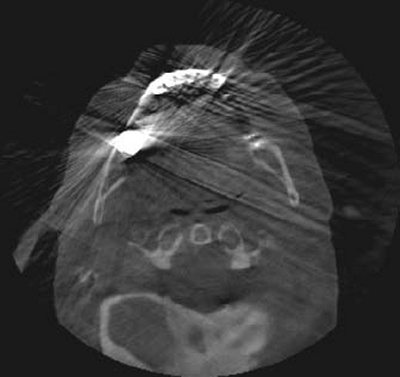
A common problem in CT images is streak artifacts caused by the presence of high-attenuation objects in the field of view. Metallic objects such as dental restorations, surgical plates and pins and radiographic markers can cause this type of the artifact. Since the metal in these materials highly attenuate the x-ray beam, the attenuation values of objects behind the object are incorrectly high. Due to the reconstruction of the cone beam image, the metal causes the effect of bright and dark streaks in CT images which significantly degrade the image quality. In conventional CT images metallic artifacts traverse the object in the direction of the gantry and only at the level of the high attenuation object. In CBCT, the metallic streak artifacts occur in all directions from the high attenuation object because of the cone-shaped beam.
Motion Artifacts
Motion Artifacts
Patient motion can cause misregistration artifacts within the image. Because of the relatively long acquisition times (compared to conventional radiography) and volumetric image acquisition, motion artifacts are common in CBCT. These artifacts can be attributed to improper patient stabilization.
Small motions cause image blurring and larger physical displacements produce artifacts that appear as double images or ghost images. This results in poor overall image quality. Since the resolutions of the present CBCT are very high, ranging from 0.08mm-0.4mm, even small motions can have a detrimental effect on image quality.
Conclusion
The artifacts presented are some of the common artifacts seen in CBCT images. Care should when acquiring CBCT images to keep image artifacts to a minimum by selection of optimum scanning parameters and careful patient positioning and stabilization. When interpreting the images it is also important to recognize imaging artifacts to prevent inaccurate diagnoses.
I'd like to thank Dr. Bruno Azevedo and Dr. Pirkka Nummidoski for their contributions to this article.
References
Julia F. Barrett and Nicholas Keat: Artifacts in CT: Recognition and Avoidance. RadioGraphics, Nov 2004; 24: 1679 - 1691.
Mehran Yazdi, and Luc Beaulieu: Artifacts in Spiral X-ray CT Scanners: Problems and Solutions. International Journal of Biological and Medical Sciences, 2008; 3: 135-139.
Julia F. Barrett and Nicholas Keat: Artifacts in CT: Recognition and Avoidance. RadioGraphics, Nov 2004; 24: 1679 - 1691.
Mehran Yazdi, and Luc Beaulieu: Artifacts in Spiral X-ray CT Scanners: Problems and Solutions. International Journal of Biological and Medical Sciences, 2008; 3: 135-139.


