
Manufacturing Splints for Orthognathic Surgery
|


|
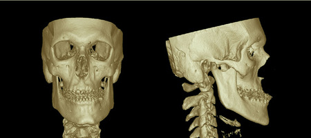
Fig. 1: CT scan showing the 3D skull of a patient with class III dysgnathia. The patient is wearing brackets which results in artifacts around the teeth.
Skull Segmentation
All planning steps in CAS are based on virtual segmentation procedures, which are necessary for performing repositioning. By using predefined Le Fort I and Obwegeser-Dal Pont osteotomy lines, the upper and lower jaws can be segmented (Fig. 2).
All planning steps in CAS are based on virtual segmentation procedures, which are necessary for performing repositioning. By using predefined Le Fort I and Obwegeser-Dal Pont osteotomy lines, the upper and lower jaws can be segmented (Fig. 2).
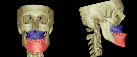
Fig. 2: Dataset after segmentation of the upper (blue) and lower (red) jaws with regard to the Le Fort I and Obwegeser-Dal Pont osteotomy lines).
Artifacts are not always avoidable owing to preoperative orthodontic treatment, including dental brackets or dental restorations. This prevents an accurate adjustment of the upper and lower tooth rows to determine the planned new occlusion. To solve this problem, 2 possible solutions are presented:
Tomography. One solution involves scanning the plaster model of the upper and lower jaws during the patient scan. A CBCT scan is shown in Fig. 3. Both models are put together in the desired occlusion and placed over the patient's head during the CT scan. The whole dataset is imported into the software, where a tool is available for separating this dataset back into 2 separate sets (skull dataset and dental model dataset), which is necessary for the further planning steps. After segmentation of the upper and lower tooth rows of the model dataset, a special export tool allows the generation of three Standard Tessellation Language (STL) files of the segmented parts. Two files contain the single tooth rows, and the third contains the determined new occlusion (Fig. 3).
Tomography. One solution involves scanning the plaster model of the upper and lower jaws during the patient scan. A CBCT scan is shown in Fig. 3. Both models are put together in the desired occlusion and placed over the patient's head during the CT scan. The whole dataset is imported into the software, where a tool is available for separating this dataset back into 2 separate sets (skull dataset and dental model dataset), which is necessary for the further planning steps. After segmentation of the upper and lower tooth rows of the model dataset, a special export tool allows the generation of three Standard Tessellation Language (STL) files of the segmented parts. Two files contain the single tooth rows, and the third contains the determined new occlusion (Fig. 3).
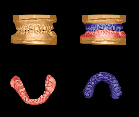
Fig. 3: Cone-beam CT dataset of plaster models of the upper and lower tooth rows before (top left) and after (top right) segmentation. A special export tool allows the generation of 3 STL files: one of the segmented lower jaw (bottom left), one of the upper jaw (bottom right), and one of the determined new occlusion (top right).
Surface scan. Another solution consists of scanning the plaster models using a dental surface scanner. By scanning each single model (lower and upper jaws) and the situation of both models in the determined new occlusion, 3 scanning STL files are generated (Fig. 4).
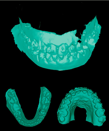
Fig. 4: Surface scans (STL files) of the plaster models, including the upper jaw (bottom right), the lower jaw (bottom left), and the models in the determined new occlusion (top).
Model-skull fusion
In the following step, the acquired STL files are imported into the 3D modeling software. By defining at least 3 reference points for each virtual tooth row and their corresponding points in the skull dataset, a precise overlap of the generated STL files and their corresponding anatomic structures in the skull dataset is achieved. Note that, at this planning step, the file containing the determined new occlusion is not required, because the repositioning of the upper jaw will be encoded by producing a preliminary dental splint (Fig. 5).
In the following step, the acquired STL files are imported into the 3D modeling software. By defining at least 3 reference points for each virtual tooth row and their corresponding points in the skull dataset, a precise overlap of the generated STL files and their corresponding anatomic structures in the skull dataset is achieved. Note that, at this planning step, the file containing the determined new occlusion is not required, because the repositioning of the upper jaw will be encoded by producing a preliminary dental splint (Fig. 5).
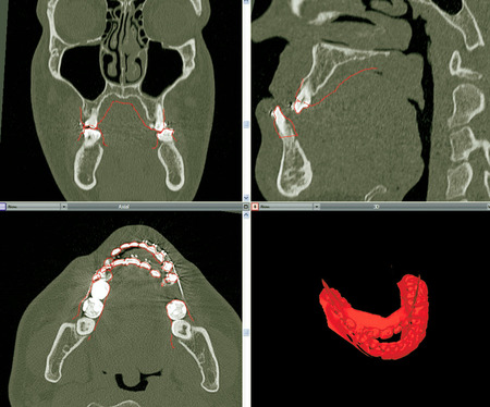
Fig. 5:The situation of the scanned models of the upper and the lower jaws after virtual alignment to the skull dataset. Note that the third model representing the determined occlusion is not yet included, because the repositioning of the upper jaw will be encoded by producing a preliminary dental splint.
An important function for further planning is the possibility of attaching the virtually aligned models to the segmentations of the upper and lower jaws in the skull dataset. This guarantees that movements made for the planned repositioning in the skull dataset (upper and lower jaw in the skull dataset) will be followed by the aligned scan models.
Definition of symmetry planes
The whole skull dataset is manually aligned to the symmetry planes using the multiplanar view. Automatic procedures would have the disadvantage of including asymmetrical parts of the skull in the calculations, which would lead to inaccuracy. The midsagittal plane was used for vertical orientation, and the Frankfurter horizontal plane was used for transversal orientation.
Repositioning: upper jaw
First, the occlusion plane of the upper jaw was defined by setting 3 points. Two points were set at the first molar teeth, and the third was placed at the contact point between the 2 middle front teeth. By attaching these points to the segmentation of the upper jaw, following of the movements carried out during the repositioning of the plane is guaranteed.
Using the multiplanar view, it is possible to reposition the upper jaw in each single direction. The upper jaw was rotated until the occlusion plane was parallel to the horizontal plane in the coronal view. In the sagittal view, an inclination was performed until it was parallel to the Frankfurter horizontal plane. In the axial view, the upper jaw can be moved in anterior and posterior directions until the required profile projection is achieved (Fig. 6).
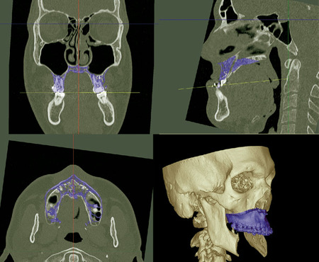
Fig. 6: Adjustment of the upper jaw (blue) considering the occlusion plane with regard to the horizontal plane (top left), the inclination (top right), and the required anterior movement (bottom left). 3D visualization of the situation after repositioning (bottom right).
It should be noted that the axial rotation of the upper jaw should not be considered at this point, because this requires orientation of the lower jaw (see next section).
Repositioning: lower jaw
To transform the actual position of the upper jaw to the lower, the third STL file containing the planned occlusion is used (Fig. 7, A). By aligning the virtual model to the repositioned upper jaw in the same way as described above, it is now possible to move the lower jaw fragment into an adequate position (Fig. 7, B). In the presented case, controlling the new position of the lower jaw led to a large deviation of the osteotomy lines, which is recognizable in the axial view (Fig. 8).
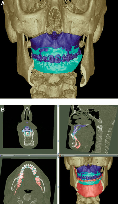
Fig. 7:A, Situation after import and adjustment of the virtual model (cyan) representing the ideal occlusion to the repositioned upper jaw (blue). B, Adjustment of the lower jaw (red) using the information from the virtual model showing the ideal occlusion.
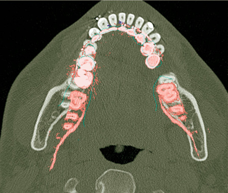
Fig. 8:Situation of the lower jaw (red) after adjustment with regard to the virtual model (green) showing the ideal occlusion. A deviation of the axial rotation is visible at the mandible angle in the region of the osteotomy (right to left).
To correct this, both segmented parts (upper and lower jaw) were linked and rotated axially. The rotation center was placed at the front teeth, because the front teeth appeared to be well positioned in the midsagittal plane.
Splint production
First splint. To produce the first splint, the repositioned upper jaw and the original lower jaw with their aligned STL files were used to transform the necessary information into a virtual splint. This was selected from a database including several different sizes of virtual "blank splints" (Fig. 9). A correctly sized splint was selected and placed between the tooth rows.
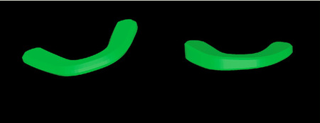
Fig. 9: Two virtual "blank splints," which can be used for planning. Left: plane splint; right: cuneiform splint.
Second splint. To produce the second splint, the repositioned upper and lower jaws with their aligned STL files were used. A second virtual splint was selected and also placed between the tooth rows (Fig. 10).
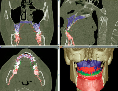
Fig. 10: Planned final situation after performing a slight rotation of the upper and lower jaws. The virtual "blank splint" (green) has been imported and set between the tooth rows.
After performing the splint placement, the software performs a boolean operation by subtracting the impressions of the virtual models from the virtual "blank splint," resulting in final splints (Fig. 11).
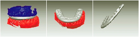
Fig. 11: Transformation of the virtual "blank splint" into a splint including the repositioning information of the jaws by performing a boolean operation. Left: subtracting the virtual upper jaw; middle: subtracting the virtual lower jaw; right: final virtual splint with tooth impressions.
After these steps, it is possible to export the virtual splints (STL files) to a 3D printer or a drilling device to produce the final splints.
Postoperative Control
In the presented case, a postoperative control CT scan was performed. Using the automatic image fusion procedure, the preoperative planning situation and the clinical outcome could be evaluated (Fig. 12).
Postoperative Control
In the presented case, a postoperative control CT scan was performed. Using the automatic image fusion procedure, the preoperative planning situation and the clinical outcome could be evaluated (Fig. 12).
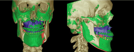
Fig. 12: Postoperative control performed by image fusion of the preoperative (brown) and postoperative (green) datasets, including the postoperative planning of the upper (blue) and lower (red) jaws.
DISCUSSION
A new technique for producing dental splints using the information obtained by virtual preoperative 3D planning has been presented. It combines the advantages of the commonly used splint technique and the possibility of precise virtual 3D planning with regard to the whole skull symmetry.
Despite the great benefits of going digital in several areas, the human sense of touch is not yet replaceable without great effort when fine adjustment of objects is required.12,13 By continuing to use common plaster models to determine the ideal occlusion, the surgeon need not abandon haptic involvement. Thereby, important details of interdigitation, occlusal anatomy, and wear facets can be precisely transformed into the virtual situation. This prevents the false appearance of crossbite or overjet on the monitor screen, which is challenging and time consuming when planning is only carried out virtually.6
On the other hand, the additional advantages of the digital planning devices and software tools, such as accuracy, efficiency and ease of measurement, and diagnostic procedures, are included. Simulating the operation on plaster models is difficult owing to the lack of a real link between the cephalometric analysis and the commonly performed plaster model surgery. Rotational and translational movements of the plaster models are insufficiently controlled during the model surgery stage. Finally, the splint, which transfers the final relative position of the maxilla to the mandible, summates all of the errors of the previous stages.10 By considering the whole skull asymmetry and not only the situation presented by plaster models, a large anatomic region can be included in the planning process.
Laser surface scanning and rapid prototyping is commonly used in industry and medicine as a noninvasive alternative for generating 3D computerized images and models. The accuracy of dental surface scanners and the rapid prototyping procedures for orthognathic surgery is now beyond all question.14,15 Despite the ability to only scan visible surfaces, the advantages of ease of use, self-calibration, and automatic image distortion correction make generating 3D computerized images very convenient.16Additionally, the plaster models can be discarded after the digitalization is done. The patient records are instantly available on the computer, and large and expensive storage areas are no longer necessary.6 When models or splints are needed, modern 3D printers allow fast, easy, and cheap (€0.20/cc) production in different materials.
Limitations of this technique
In the presented case, enough space was found between the 2 tooth rows to allow insertion of the virtual splint without moving the lower jaw. However, in cases where an overlap occurs owing to the repositioning of the upper jaw, a vertical opening of the lower jaw is unavoidable. Therefore, it is possible to define a rotational axis through both mandible joints, which approximately simulates the movement of the lower jaw. However, this simple rotation does not really take into consideration the individual anatomic situation of each patient.
Another limitation of this technique is the impossibility of determining the vertical orientation of the upper jaw. Here, conventional techniques, such as measuring the distances between the infraorbital foramen and the canine teeth, still have to be used to determine the accurate vertical level. Using the virtual planning software, the length values can be easily acquired after the accurate placement of the upper jaw has been carried out. A recently published technique includes Kirschner wires for intraoperatively detecting the correct placement of the upper jaw.9
Hardware components such as the dental surface scanner or the 3D printer demand large initial costs. This is the reason an alternative method for scanning the plaster models using CBCT or CT during data acquisition from the patient was demonstrated. When splint production is available, the virtual splint data could be sent to an institution offering a printing service.
REFERENCES
1. Stamm T, Meyer U, Meier N, Ehmer U, Joos U. Public domain computer-aided surgery (CAS) in orthodontic and maxillofacial surgery. J Orofac Orthop 2002;63:62-75.
2. Wortche R, Hassfeld S, Lux CJ, Mussig E, Hensley FW, Krempien R, et al. Clinical application of cone beam digital volume tomography in children with cleft lip and palate. Dentomaxillofac Radiol 2006;35:88-94.
3. Ziegler CM, Woertche R, Brief J, Hassfeld S. Clinical indications for digital volume tomography in oral and maxillofacial surgery. Dentomaxillofac Radiol 2002;31:126-30.
4. Macchi A, Carrafiello G, Cacciafesta V, Norcini A. Three-dimensional digital modeling and setup. Am J Orthod Dentofacial Orthop 2006;129:605-10.
5. Whetten JL, Williamson PC, Heo G, Varnhagen C, Major PW. Variations in orthodontic treatment planning decisions of class II patients between virtual 3-dimensional models and traditional plaster study models. Am J Orthod Dentofacial Orthop 2006; 130:485-91.
6. Stevens DR, Flores-Mir C, Nebbe B, Raboud DW, Heo G, Major PW. Validity, reliability, and reproducibility of plaster vs digital study models: comparison of peer assessment rating and Bolton analysis and their constituent measurements. Am J Orthod Dentofacial Orthop 2006;129:794-803.
7. Miller RJ, Derakhshan M. Three-dimensional technology improves the range of orthodontic treatment with esthetic and removable aligners. World J Orthod 2004 Fall;5:242-9.
8. Mischkowski RA, Zinser MJ, Kubler AC, Krug B, Seifert U, Zoller JE. Application of an augmented reality tool for maxillary positioning in orthognathic surgery-a feasibility study. J Craniomaxillofac Surg 2006;34:478-83.
9. Gil JN, Claus JD, Manfro R, Lima SM Jr. Predictability of maxillary repositioning during bimaxillary surgery: accuracy of a new technique. Int J Oral Maxillofac Surg 2007;36:296-300.
10. Olszewski R, Reychler H. [Limitations of orthognathic model surgery: theoretical and practical implications.] Rev Stomatol Chir Maxillofac 004;105:165-9.
11. Yosano A, Yamamoto M, Shouno T, Shiiki S, Hamase M, Kasahara K, et al. Model surgery technique for Le Fort I osteotomy-alteration in occlusal plane associated with upward trans- position of posterior maxilla. Bull Tokyo Dent Coll 2005; 46:67-78.
12. Noroozi H. Orthodontic treatment planning software. Am J Orthod Dentofacial Orthop 2006;129:834-7.
13. Noroozi H. Introduction of a new orthodontic treatment planning software; a fuzzy logic expert system. Int J Orthod 2006;17:25-9.
14. Faber J, Berto PM, Quaresma M. Rapid prototyping as a tool for diagnosis and treatment planning for maxillary canine impaction. Am J Orthod Dentofacial Orthop 2006;129:583-9.
15. Vlaar ST, van der Zel JM. Accuracy of dental digitizers. Int Dent J 2006;56:301-9.
16. Kusnoto B, Evans CA. Reliability of a 3D surface laser scanner for orthodontic applications. Am J Orthod Dentofacial Orthop 2002;122:342-8.
aDepartment of Craniomaxillofacial Surgery, Albert-Ludwig University Freiburg.
bComputer Science and Computer Graphics Department, Albert-Ludwig University Freiburg.
cHirslanden Medical Center.
Received for publication Apr 29, 2007; returned for revision Jul 16, 2007; accepted for publication Jul 23, 2007.
© 2008 Mosby, Inc. All rights reserved. doi:10.1016/j.tripleo.2007.07.040