
Limitations of Two-Dimensional Cephalometric Analysis in Orthodontic Diagnosis and Treatment Planning: The need for Three-dimensional DiagnosisWilliam E. Harrell Jr., DMD
Board Certified Orthodontist, ABO - Alexander City, Alabama Member - Council on Information Technology (COIT) - American Association Orthodontists (AAO) Member - Standards Committee on Dental Informatics (SCDI) - American Dental Association (ADA) From the Summer 2003 AADMRT Newsletter 
Imaging Labs provide an extremely important extension of the doctor's office to include up-to-date, high quality imaging with high diagnostic yield. The goal in orthodontic diagnosis and treatment planning has been to decide a course of treatment based on the evaluation of the initial condition of the patient's anatomy evaluated from a variety of data sources. Today, the evaluation of these anatomical relationships, by the use of various twodimensional imaging modalities, such as: Photographs, X-rays and Cephalometric tracings & analysis, etc., have only given a small amount of information when compared to the "Anatomic Truth" of the patient's actual three-dimensional anatomy(1,9,10,11). Imaging labs can extend their traditional two-dimensional imaging services by providing the doctor with three-dimensional and anatomically accurate image volumes and computer models. The three-dimensional information can be generated from traditional 2D imaging sources that are calibrated and merged into a 3D "digital replica" of anatomy or can be acquired in a 3D format. This will allow for more accurate diagnosis and treatment planning, treatment monitoring, and outcomes analysis by the doctor. This is possible with the technology that is being developed by Acuscape® (Acuscape® International, Inc., (www.acuscape.com) in Glendora, CA).
Since the introduction of Cephalometrics, by Broadbent in 1931(2), orthodontists and oral surgeons have tried to analyze the relationship between the teeth, bone, and soft tissues of the face. It is important for Imaging Lab personnel to know the limitations of the two-dimensional diagnostic information, which they produce, in order to educate not only themselves, but also the doctors and staffs, which they serve. Sarver, in 1988, published an article(15) on video-cephalometric integration (combining the two-dimensional lateral video image of the patient's face to the 2D lateral cephalogram) for diagnosis and treatment planning of orthognathic surgery cases. The problems of coordinating these two different types of images, into a two-dimensional overlay, are apparent and shown in Figure 1A. |


|
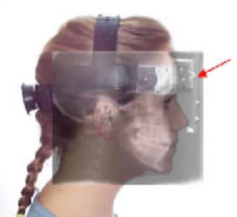
Figure 1A
Figure 1A shows the problems of combining the lateral 2D facial image of a patient and the lateral 2D Cephalogram. As we size these two separate images to "fit each other" by superimposing the profiles we can notice that the calibration targets do not line up with each other (see red arrow). Note that the calibration device has been securely attached to the head and does not move between taking the facial images and the cephalogram. This shows that the superimpositions do not represent the true anatomical relationships of the patient's hard and soft tissue anatomy.
Also if we look at Figure 1B, we can see that the round surface contour of the head (see red arrow) does not allow for the proper relationships to be represented as if the X-ray was superimposed in the midline of the face. If we are to represent to patient's anatomy "as it exists in nature", then the 2D images must be calibrated and the information should be combined in three-dimensional space in an anatomically accurate relationship by the creation of a "virtual patient".
Also if we look at Figure 1B, we can see that the round surface contour of the head (see red arrow) does not allow for the proper relationships to be represented as if the X-ray was superimposed in the midline of the face. If we are to represent to patient's anatomy "as it exists in nature", then the 2D images must be calibrated and the information should be combined in three-dimensional space in an anatomically accurate relationship by the creation of a "virtual patient".
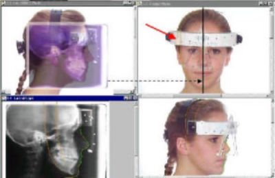
Figure 1B
Figure 2A shows the 3D face calibrated with the teeth in three-dimensional space. The frontal and lateral cephalometric x-rays are positioned at 15 cm from mid-sagittal plane, which is the relationship in which they were taken. Figure 2B you are looking at the patient's face at the 60-inch distance from which the Lateral Ceph was taken. This shows the correct relationship of the Lateral Ceph to the 3D face and teeth, at the 15 cm distance from midsagittal to film distance. The soft tissue profile and the teeth relationship line up in this perspective view, which is how the patient was positioned and how the Lateral Ceph was positioned when the Lateral Cephalometric X-ray was taken.
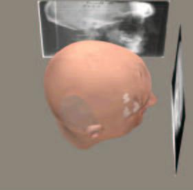
Figure 2A
|
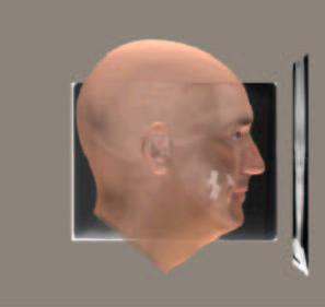
Figure 2B
|
Figure 3A shows the relationship of the face with the Frontal Ceph at the midline and the Lateral Ceph at the 15 cm distance from which it was taken. Figure 3B shows the Lateral and Frontal Cephs moved to the midline, which is where doctors assume they are making their diagnosis.
Figure 3C shows the effect of moving the Lateral Ceph to the midline and note that the Lateral Ceph does not match the face. This shows the magnification effect of moving the Ceph to the midline and the geometric effects.
Figure 3C shows the effect of moving the Lateral Ceph to the midline and note that the Lateral Ceph does not match the face. This shows the magnification effect of moving the Ceph to the midline and the geometric effects.
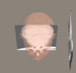
Figure 3A
|
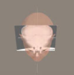
Figure 3B
|
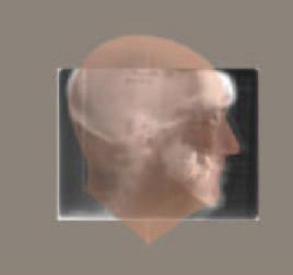
Figure 3C
|
Figure 4 is an example of the calibrated data of tooth, skeletal and soft tissue being combined into a "Virtual Patient". True three-dimensional analysis and treatment planning can be made on this type of digital computer model of patient anatomy. This type of 3D output to the doctor can be viewed from any angle, sliced to reveal underlying anatomy, and individual teeth and sections of bones, etc. can be manipulated by the doctor for both orthodontic and orthognathic surgery treatment planning purposes.
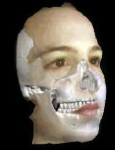
Figure 4: The "Virtual Patient"
The only true three-dimensional representation, which orthodontists have routinely used for decades, has been the plaster study models made from impressions of the teeth. These study models have either been trimmed to standard trimming protocol and/or mounted on articulators to allow for a more accurate three-dimensional relationship to the anatomy of the patient.
There has been recent interest in the conversion of the plaster casts or impressions of the teeth into electronic digital study models to aid in diagnosis, treatment planning and for storage considerations (i.e. E-Models®, OrthoCad®).
There has also been the development of an intraoral scanning device, which allows for the scanning of the crowns of the teeth directly in the mouth without the need for impressions (i.e. OraMetrix® SureSmile technology). While these forms of 3D data of the anatomy of the teeth are a great stride forward, there are limitations of not having the root, skeletal and soft tissue anatomy in three-dimensions. Some limited measuring capability is present and storage considerations are helpful, but the accuracy of manually measuring a 3D representation on the computer screen is still questionable.
Linear projective transformation
In order for imaging lab personnel to more fully understand the limitations of projecting a 3D object (i.e. the human head) onto a 2D X-ray film or even a 2D photograph, one needs to understand the concept of "Linear Projective Transformation"(13). In Figure 5A all the lines A, B & C are the same length, but due to the position and orientation of these lines in 3D space, they are projected onto the film plane as "different" lengths (see the red, yellow, blue lines projected onto the film plane). So any measurement made on the film is not correct when compared to the "Anatomic Truth". In Figure 5B you will notice that all the lines are of different lengths, but are projected onto the 2D film as the same length and in the same location (see the red line projected onto the film plane). Again, the true measurements are not represented because of linear projective transformation (geometric projection errors). Even if we view the patient's anatomy from a Lateral Ceph AND a Frontal Ceph, we still do not have a true understanding of the 3D anatomy and each 2D projection has its own linear projective transformation errors(13) and landmark identification errors(3). Enlow(14) said: "Traditional cephalometrics was developed before there was a working understanding of the biological processes of facial growth. Now with the imminent advent of (1) very advanced computer 3-dimensional imaging, and effective visualization, and (2) with our markedly advancing and really meaningful understanding of the biology of craniofacial development, the marriage of (1) and (2) is going to turn craniofacial diagnosis inside out within the foreseeable future.... The near future will be based on the actual biology of an individual's own craniofacial growth and development, and it will be determined by a 3-dimensional evaluation based on that person's actual morphogenic characteristics, not simply developmentally irrelevant radiographic landmarks."
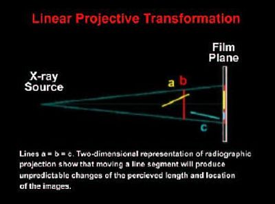
Figure 5A
|
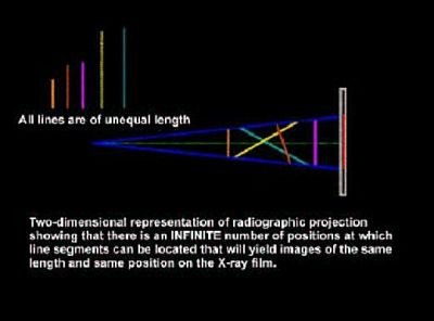
Figure 5B
|
An important research study was done at the University of California San Francisco by Greg Adams, DMD, David Hatcher, DDS & Arthur Miller, PhD. It was presented as an abstract in the July 2002 issue of the AJODO(1). The title was "Comparison between traditional two-dimensional cephalometry and a three-dimensional approach". The abstract reads: "The 2-dimensional cephalogram is the standard used by orthodontists to assess skeletal, dental, and soft tissue relationships. This approach is based on 2-dimensional views of 3-dimensional objects. The purpose of this research project was to compare the standard 2-dimensional imaging analysis (cephalometry) with a new 3-dimensional imaging system (Acuscape® Sculptor) by using full-head x-rays. The measurements obtained from both the 2-dimensional and 3-dimensional analyses of the x-rays were compared with physical measurements made with precision calipers from 9 dried human skulls. Radiopaque markers (Beekley, Bristol, Conn) were used to identify 13 specific skeletal landmarks; 76 measurements taken from the skulls with the physical calipers served as the gold standard. The Bland-Altman method was used to statistically evaluate the data. Repeated measurements directly from the skulls indicated a high average intra-class correlation (0.995) and a high reliability (variance, 0.054 mm2; standard deviation, 0.237 mm). The 2-dimensional measures from the x-rays indicated a much higher variability, with a larger mean standard deviation (6.94 mm) compared with the 3-dimensional measures (0.54 mm). The 2-dimensional analysis demonstrated a general lack of precision compared with the 3-dimensional analysis (points clustered within 0.5 mm). Comparison of the ranges between the 2 systems to the gold standard demonstrated a much larger magnitude of potential error inherent in the 2-dimensional system. There was no relationship between the length of the measurement and the magnitude of the error. This study suggests that the 3-dimensional program tested in this research can become an effective and accurate tool in evaluating the real changes in growth and development of the craniofacial skeleton."
These large differences in the 2D vs the 3D data are due to head positional errors, linear projective transformation errors, and magnification. In order to represent the patient's anatomy accurately, we must start moving towards creating our diagnostic information in three-dimensions. Time, the 4th dimension, which includes response to treatment, aging, degenerative changes, growth and development, etc. can also add greatly to the information we can gain when evaluating the true spatial dimensional accuracy of anatomy (3D) of our patients.
This 3D model of patient anatomy in Figure 6 shows a common problem of landmark identification. The insert shows the landmark Gnathion located at the outer contour of the chin, between Pogonion and Menton. As the 3D model is rotated one can see that the landmark Gnathion, is not located at the midline, it is actually located more laterally due to the contour of the anatomy of this area.
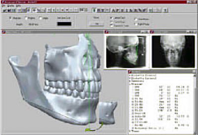
Figure 6
|
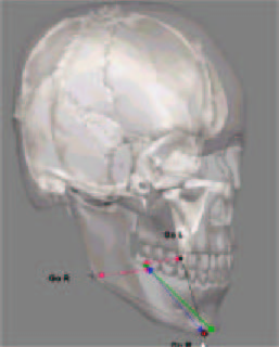
Figure 7
|
If we make the 3D skull transparent then we can evaluate how an abstraction of the anatomy of the Mandibular Plane (Go-Gn) is represented. The green line represents the traditional Go-Gn, which is an average of the right and left sides. The Green dots at each end represent the "location" of the landmarks Gonion and Gnathion. When we average bilateral landmarks not only do we loose the bilateral information of the patient, but also we cannot truly evaluate any asymmetry of the mandible that may exist. Let's analyze the bilateral structure of this model in Figure 7. First look at where the Gonion Right (see Go R in Figure 7) and the Gonion Left (see Go L in Figure 7) is located on the mandible. When these are "averaged to the midline" (the Red arrows), as in traditional cephalometrics, we come up with a midline point called "Gonion" (see green dot between the red arrows at the midline). In Figure 6 we saw that the location of the true Gnathion is actually more lateral than we thought (in Figure 7, see red dot on chin and called Gn R for the "Right Gnathion"). If one now connects the "Averaged Gonion" (green dot) to where the actual Gnathion is located (Red dot), we now have the "Blue Line" which represents another "Go-Gn" Mandibular Plane. Why is this important? Look at Figure 8.
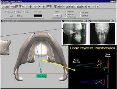
Figure 8
Figure 8 is the 3D model from a "Sub-Mental Vertex" View. The averaged Gonion (Go Avg) is the midline average of the Right and left Gonions (Mid point of the Red line connecting Right and Left Gonion). The Green line represents the traditional Cephalometric line Go-Gn. This represents one of the ways we symbolize the "Mandibular Plane" in traditional 2D Cephalometrics. The "Blue Line" shows a Mandibular Plane represented by averaging the Right and Left Gonions and where the X-ray beam projects Gnathion at a more lateral position than the midline. This relates directly to the concept of "Linear Projective Transformation" which means that different line representations of Mandibular Plane anatomy (Green vs Blue vs the more accurate representation by the Black lines) may actually be projected onto the 2D Ceph as THE SAME LINE and same length, when they are actually completely different when considering the "Anatomic Truth".
Conclusion
All patient;s anatomy is three dimensional, yet most of the diagnostic data and analysis today, even with the advent of digital capture devices and computerized analysis tools, still remains two-dimensional. Patients also change over time, which is the 4th dimension. These changes can be growth & development changes (normal or abnormal or growth modification), treatment intervention changes, aging and/or degenerative types of changes, etc. The three-dimensionality of patients plus how they change over time is critical to the accuracy in diagnosis, treatment planning, monitoring treatment response, and treatment outcome evaluation.
Maxillofacial Imaging Labs are in an ideal position to offer extended services, such as three-dimensional digital modeling made from the traditional 2D images, to their doctor base by educating the doctors on the differences and limitations of traditional 2D imaging and analysis alone. These higher quality services, such as 3D modeling, that labs can provide, will also give the doctor the ability to have more accurate three-dimensional information upon which to make their diagnostic and treatment planning decisions.
Future
The future of representing orthodontic patient anatomy three-dimensionally (The "Virtual Patient"), as they exist in nature, allows for more accurate diagnosis and treatment planning, outcomes analysis, and monitoring treatment changes over time(10,12). Three-dimensional modeling of patient anatomy allows for engineering principles to be applied to such areas as local and general stress analysis of the stomatognathic system(4,5,6), analysis of asymmetry and how it may affect function(7), TMJ loading and occlusal forces(6,7), reconstruction in Oral and Maxillofacial surgery(8) and functional studies on dynamic 3D models(17) (seewww.acuscape.com/hannam2.html), will help us to understand the dynamic relationship of the anatomy which orthodontists, oral surgeons and dentists affect everyday in their practices. Imaging Laboratories can play an integral part in education and improving the routine diagnostic information that they provide to doctors on a daily basis.
REFERENCES
- Adams GL, Hatcher DC, Miller AJ, Comparison between traditional two-dimensional cephalometry and a three-dimensional approach, Division of Orthodontics, University of California, San Francisco, AJODO, Abstract, Vol. 22, Number 1, Page 117, July 2002
- Broadbent BH. A new x-ray technique and its application to orthodontia. Angle orthod 1:45-66, 1931.
- Baumrind S, Frantz RC: The reliability of head film measurements. 1. Landmark identification. Am J Orthod. Aug;60(2):111-27, 1971
- Hatcher, D: Maxillofacial Imaging, Occlusion: Science & Practice, Ed. Charles McNeill, Quintessence Publishing, 349-364, 1997.
- Hatcher, D., et. al.: Engineering Principles and Modeling Strategies, Occlusion: Science & Practice, Ed. Charles McNeill, Quintessence Publishing, 153-164, 1997.
- Hatcher, D., et. al. Distribution of Local and General Stresses in the Stomatic System, Occlusion: Science & Practice, Ed. Charles McNeill, Quintessence Publishing, 259-270, 1997.
- Hatcher, D., et. al., Maxillofacial Relationships: Mandibular Asymmetry, Occlusion, and Imaging, Occlusion: Science & Practice, Ed. Charles McNeill, Quintessence Publishing, 273-293, 1997.
- Hatcher, D., Diagnostic Imaging, Reconstruction Preprosthetic Oral and Maxillofacial Surgery, EDS. Davis H., Fonseca R, Philadelphia, WB Saunders, 86-123, 1995.
- Quintero, JC, Trosien A., Hatcher D., Kapila S., Craniofacial imaging in Orthodontics: Historical perspective, current status and future developments, The Angle Orthodontist, vol 69 No. 6, 491-506, 1999.
- Harrell, W, Hatcher, D, Bolt, R: ?In Search of Anatomic Truth: 3D Digital patient modeling and the future of Orthodontics?, AJODO, Vol. 122 Number 3, p. 125-130, Sept 2002
- Hatcher, DC, Harrell, WE: Diagnosis Goes Digital, In: Information Technology and Orthodontic Treatment, Moyers Symposium 2002, Editor: McNamara, University of Michigan, 2003.
- Harrell, WE: Future of Imaging in Orthodontics, In: Essentials for Orthodontic Practice, Chapter 15, 2002, pg. 405-413, Editors: Drs. Michael Riolo & James Averey, 2003.
- Tsao DH, Kazanoglu A, McCasland JP, Measurability of radiographic images, Am J Orthod Sept;84(3):212-6, 1983
- Donald Enlow Editorial AJODO Feb;117(2):147-148, 2000
- Sarver, D., Johnston, M., Matukus, V.: Video Imaging in Orthognathic Surgery, J. Oral Maxillofac Surg., 46:939-945, 1988.
- Sarver, D: Esthetic Orthodontics & Orthognathic Surgery, Mosby, 1998.
- Langenbach GEJ, Hannam AG. The role of passive muscle tensions in a three- dimensional dynamic model of the human jaw. Arch Oral Biol 1999;44:557-73.