
Use of conventional cT and cone beam for
|


|

There are many reasons to utilize three dimensional computed tomography in dentistry, and most all involve the ability to better assess anatomy, whether for diagnosing pathology or for potential placement of dental implants. Often in the course of evaluation, a CT scan is advised to determine the existing condition of the maxillary or mandibular bone. The ability to process three distinct images; (1) panoramic, (2) axial, and (3) cross-sectional allows for a higher level of appreciation than can be achieved by any two dimensional imaging device, and frequently leads to surprises.
A CT image will differentiate problems in the maxillary sinus, that could have remained undetected. Unique to the maxilla, are the bilateral sinuses, and nasal cavity which come in various sizes and shapes. An axial view of an asymptomatic patient?s maxillary arch revealed significant pathology as represented in FIGURE 1. The left maxillary sinus was perfectly clear, while the right sinus was completely occluded. Additionally, when a sinus bone augmentation procedure is contemplated, a CT scan helps visualize the volume of bone required, as well as potential asymmetries that may exist. Another interesting case yielded three surprises when the patient was being evaluated for a sinus lift procedure. FIGURE 2 reveals another partially occluded left maxillary sinus where the soft tissue polyps measured over 16mm in vertical height above the sinus floor. Perhaps more striking are two separate radiopaque masses that seemed to be attached to the right medial sinus wall. These mineralized, round lesions were well defined, with a hard cortical outer plate surrounded by more trabecular bone in the middle. These calcified masses, and the polyps were significant radiological findings, unbeknownst to the patient, and affected the final treatment plan for the patient.
A CT image will differentiate problems in the maxillary sinus, that could have remained undetected. Unique to the maxilla, are the bilateral sinuses, and nasal cavity which come in various sizes and shapes. An axial view of an asymptomatic patient?s maxillary arch revealed significant pathology as represented in FIGURE 1. The left maxillary sinus was perfectly clear, while the right sinus was completely occluded. Additionally, when a sinus bone augmentation procedure is contemplated, a CT scan helps visualize the volume of bone required, as well as potential asymmetries that may exist. Another interesting case yielded three surprises when the patient was being evaluated for a sinus lift procedure. FIGURE 2 reveals another partially occluded left maxillary sinus where the soft tissue polyps measured over 16mm in vertical height above the sinus floor. Perhaps more striking are two separate radiopaque masses that seemed to be attached to the right medial sinus wall. These mineralized, round lesions were well defined, with a hard cortical outer plate surrounded by more trabecular bone in the middle. These calcified masses, and the polyps were significant radiological findings, unbeknownst to the patient, and affected the final treatment plan for the patient.
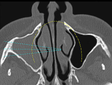
Figure 1: Axial CT scan of maxillary sinus showing occlusion of right side.
|
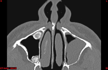
Figure 2: Axial CT revealing occlusion of the left sinus, and two calcified masses in the left sinus.
|
Further advances in CT scanning software allow for a fourth image, which can be processed to yield even more information for the clinician. A three-dimensional representation can be virtually displayed on the screen, allowing for rotation, zoom, transparency, and axial or cross-sectional slices through the image (SIM/Plant Version 9.x, Materialise, Glen Burnie, MD). The ability to interact in 3-D afforded by faster computer processors and graphic cards, is a huge step forward in the evolutionary process. The maxillary arch as visualized in 3-D, can be rotated into the best position, and a slice created through the cross-section of the sinus where the calcified mass could be more closely examined [FIGURE 3].
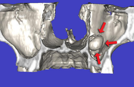
Figure 3: Reformatted 3-D view with cross-sectional slice showing calcified mass within sinus.
|
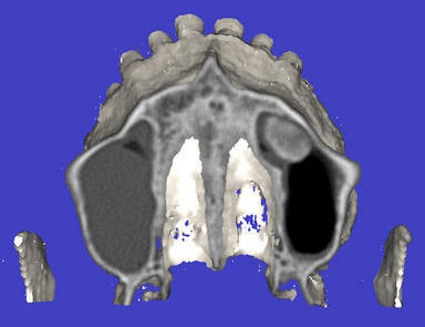
Figure 4: Axial slice through 3- D image reveals additional information about the sinus lesion.
|
The red arrows point to the outer aspects of the mass, which seemed to be "floating" air. An axial slice through the advanced three dimensional model reveals the inner aspects of the right side calcification, and the polyps located in the contra-lateral sinus [FIGURE 4].
These are images that most clinicians have never seen, and when utilized correctly vastly improve diagnosis and treatment planning potentials. Early in the evolution, CT scan film improved the diagnostic capability over conventional two dimensional images provided by panoramic or periapical radiography. Interactive CT has proved to be an invaluable and indispensable progression of the technology2.
When planning to do a sinus augmentation procedure, interactive tools allow for a simulated graft to be placed, giving the clinician an opportunity to assess the volume of bone needed to surround and support the implant. This volume (shaded green) appears in both the two dimensional cross-sectional image [FIGURE 5], and the three dimensional reformatted image [FIGURE 6]. The proposed graft is created when the interactive software calculates the shape and volume required to fill the sinus, and is evident in true 3-D when the maxilla is removed from view [FIGURE 7]. This information allows clinicians to determine in advance how much graft material is needed for each procedure. In addition, if a post-operative CT scan is desired, further information is provided to show how the implant was placed within the new volume of bone created [FIGURE 8].
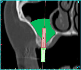
Figure 5: Software planning allows a simulated sinus graft procedure to be contemplated in this cross-sectional view.
|
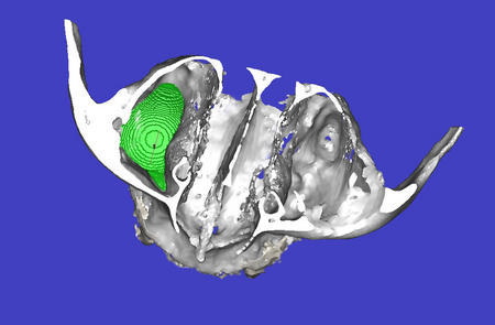
Figure 6: The occlusal view of the 3-D image shows the right sinus filled with the simulated graft volume.
|
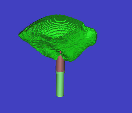
Figure 7: The implant with surrounding graft volume seen alone.
|
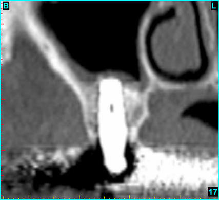
Figure 8: Post operative cross-sectional view of implant placed within a grafted sinus.
|
Images like the ones presented in this article are great teaching tools, and in the author's opinion, should be taught at the dental school as part of modern radiological methodology and interpretation. For those schools who did not have the funding for a true CT scan machine and have chosen to purchase recently available and less expensive CBCT machines, teaching these concepts is easier than ever. As an example, to understand how teeth truly exist in the bone, and how the two arches relate, what could be a better illustration than scanning both arches at the same time? FIGURES 9 and 10 illustrate the cross-sectional images of the anterior and posterior teeth in occlusion utilizing an early I-CAT CBCT (Imaging Sciences International, Hatfield, PA).
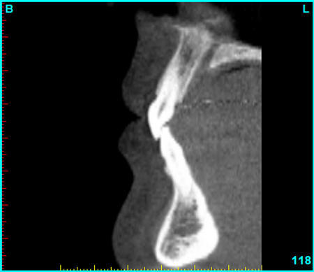
Figure 9: Cross-sectional anterior view of both arches scanned at the same time.
|
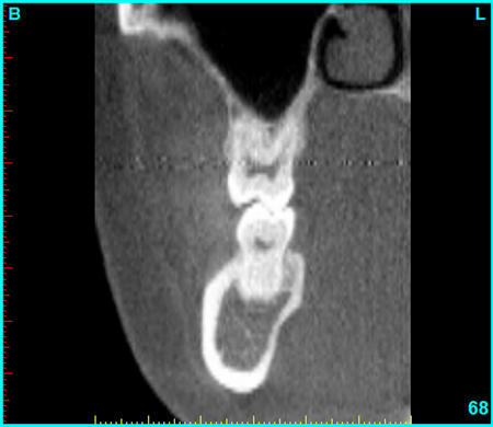
Figure 10: The posterior view gives information of the tooth to tooth position.
|
The ramifications should be obvious to all in the academic environment, and early adapters are at an advantage, resulting in students who graduate with a greater understanding and ability to diagnose and treatment plan.
Surgeons can plan routine or complex impaction cases with greater confidence when CT scans are part of the diagnosis phase3-5. A routine panoramic radiograph detected a horizontally impacted tooth located in the premolar area of the right mandible [FIGURE 11]. Without three-dimensional tomography it would be difficult to determine the spacial position of this impacted tooth in relation to the surrounding teeth and inferior alveolar nerve. The cross-sectional series shown clearly delineates the tooth position and its proximity to the adjacent tooth roots, and indicates the location of the perforation of the facial cortical plate [FIGURE 12]. This can also be appreciated in the axial view which reveals the full contour of the embedded tooth [FIGURE 13]. The three dimensional representation may be beneficial in planning the most ideal surgical access to remove the tooth without damaging encompassing structures [FIGURE 14].
Surgeons can plan routine or complex impaction cases with greater confidence when CT scans are part of the diagnosis phase3-5. A routine panoramic radiograph detected a horizontally impacted tooth located in the premolar area of the right mandible [FIGURE 11]. Without three-dimensional tomography it would be difficult to determine the spacial position of this impacted tooth in relation to the surrounding teeth and inferior alveolar nerve. The cross-sectional series shown clearly delineates the tooth position and its proximity to the adjacent tooth roots, and indicates the location of the perforation of the facial cortical plate [FIGURE 12]. This can also be appreciated in the axial view which reveals the full contour of the embedded tooth [FIGURE 13]. The three dimensional representation may be beneficial in planning the most ideal surgical access to remove the tooth without damaging encompassing structures [FIGURE 14].
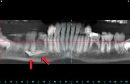
Figure 11: Panoramic radiograph reveals a horizontally impacted mandibular tooth.
|
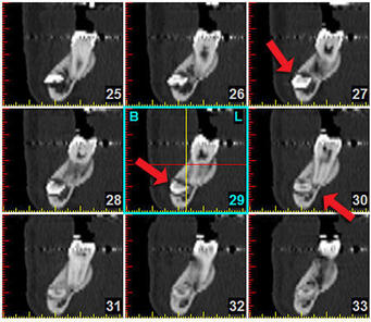
Figure 12: A consecutive series of cross-sectional images can detect the perforation of the cortical plate, and proximity to the adjacent root structures.
|
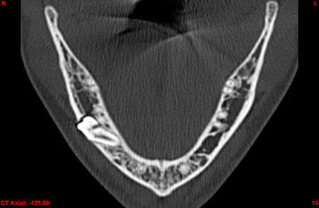
Figure 13: The axial view reveals the horizontal tooth position very precisely
|
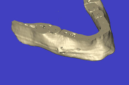
Figure 14: The 3-D image is useful in the planning phase for the eventual surgical procedure.
|
When advanced interactive features are applied to the 3D image, the axial view is maximally enhanced [FIGURE 15]. The tools illustrated can be effective in complex cases, and routine cases as well.
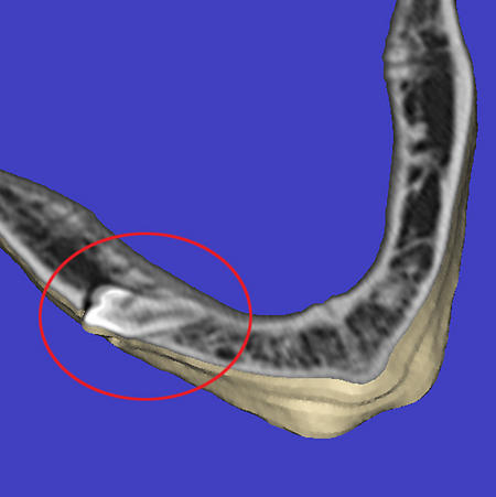
Figure 15: Slicing through the 3-D image in an axial direction is additionally revealing.
CT imaging can avoid many of the potential problems that arise from a lack of understanding of the underlying anatomical structures. Implants can be placed at the wrong angle or inclination, perforate the cortical plates, or pierce through vital nerves. Most all of these examples can be avoided with pre-surgical planning using CT imaging.
FIGURE 16 illustrates a three dimensional image of the mandible. At one time there were eight implants, of which five had failed. Arrows indicate the defects within the mandible created when two of the implants failed to integrate. Three implants remain, along with one natural tooth which is also failing. The 3-D view reveals the path of the mandibular nerve as it exits through the mental foramina. Close inspection from the occlusal view of the distal defect would show that there was clear communication between the residual socket and the superior aspect of the inferior alveolar nerve. Fortunately, the parasthesia was transient and disappeared.
FIGURE 16 illustrates a three dimensional image of the mandible. At one time there were eight implants, of which five had failed. Arrows indicate the defects within the mandible created when two of the implants failed to integrate. Three implants remain, along with one natural tooth which is also failing. The 3-D view reveals the path of the mandibular nerve as it exits through the mental foramina. Close inspection from the occlusal view of the distal defect would show that there was clear communication between the residual socket and the superior aspect of the inferior alveolar nerve. Fortunately, the parasthesia was transient and disappeared.
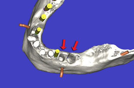
Figure 16: 3-D image showing existing implants, proposed implant sites, and sites where two implants had failed in the mandible (see arrows).
After careful evaluation of the remaining bone, in all views, additional implant sites were chosen. FIGURE 17 shows that the bone has been hidden from view, leaving an unobstructed view of the planned implants in relation to the path of the inferior alveolar nerve. Advances in the software allow clinicians to trace the path of the nerve, an essential tool to help avoid potential catastrophe. The three original remaining implants can be seen in the center of FIGURE 17. Note that the distal most implant is not parallel to the other two, and is in fact touching the middle implant. The original implants were placed using only a panoramic radiograph.
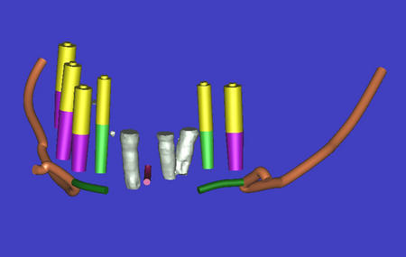
Figure 17: Removing the bone allows an unobstructed view of the inferior alveolar nerve, the virtual implants, and the existing implants of which two are touching.
In conclusion, CT imaging is a vital imaging modality that empowers the clinician with a unparalleled view of the patient. The original CT scan film, although still popular, has now been superseded with digital data that allows for interactive assimilation for diagnosis and treatment planning purposes. Conventional CT radiography has now expanded to include less expensive alternatives like the I-CAT, NewTom (Aperio Services LLC, Sarasota, FL), or CB MercuRay (Hitachi Medical Group, Tokyo, Japan) CBCT with claims of decreased radiation while maintaining accuracy. Additional machines are on the way to the marketplace from other well known manufacturers. While obvious, CT imaging is not limited to dental implant planning, and various examples were presented to illustrate diagnostic capabilities to assess pathology, sinus bone grafting procedures, and spacial positioning of impacted teeth.
Using CT imaging to evaluate potential implant receptor sites in all three dimensions has been shown to be more effective than conventional panoramic or periapical radiographs. The next logical step involves the missing link which takes the planning data and translates the virtual implant positioning to a surgical guide or template to be used at time of surgery. Use of CT derived templates provides this invaluable link between the plan and the execution of the plan in the hands of the surgeon6-8 [FIGURE 18]. Providing a tooth, bone, or soft tissue borne template with metal tubes to precisely guide the intraoral drill sequence based upon the simulated implant placement treatment plan data is now a reality. However, the template design can only be as good as the original plan, which is why further education will be needed to help clinicians fully utilize this expanding technology. As accuracy of placement, immediate loading, and esthetic concerns become more important, CT imaging, CT derived template design, and the advanced software applications that aid in the planning phase will act as a further catalyst to grow the implant dentistry market.
Using CT imaging to evaluate potential implant receptor sites in all three dimensions has been shown to be more effective than conventional panoramic or periapical radiographs. The next logical step involves the missing link which takes the planning data and translates the virtual implant positioning to a surgical guide or template to be used at time of surgery. Use of CT derived templates provides this invaluable link between the plan and the execution of the plan in the hands of the surgeon6-8 [FIGURE 18]. Providing a tooth, bone, or soft tissue borne template with metal tubes to precisely guide the intraoral drill sequence based upon the simulated implant placement treatment plan data is now a reality. However, the template design can only be as good as the original plan, which is why further education will be needed to help clinicians fully utilize this expanding technology. As accuracy of placement, immediate loading, and esthetic concerns become more important, CT imaging, CT derived template design, and the advanced software applications that aid in the planning phase will act as a further catalyst to grow the implant dentistry market.
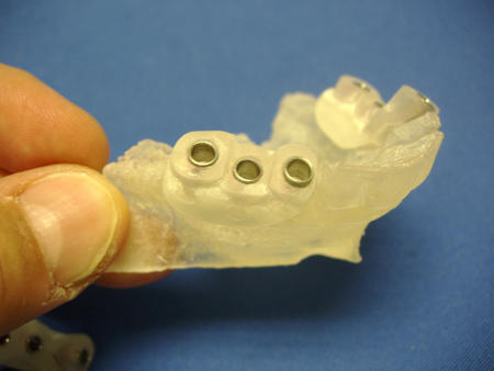
Figure 18: A CT derived bone borne surgical template accurately translates the virtual plan to the surgical site.
REFERENCES
- Sonic M, Abrahams J, Faiella R: A comparison of the accuracy of periapical, panoramic, and computerized tomographic radiographs in locating the mandibular canal. Int J Oral Maxillofac Implants 1994; 9:455-460.
- Ganz, S.D., CT Scan Technology _ An Evolving Tool for Predictable Implant Placement and Restoration. Int Mag Oral Implantol 2001;1:6_13.
- Rosenfeld AL, Mecall RA., Use of Interactive Computed Tomography to Predict the esthetic and Functional demands of Implant-Supported Prostheses. Compend Contin Educ Dent 1996;17(12): 1125-1146.
- Klein, M Cranin AN, Sirakian A. A computerized tomographic (CT) scan appliance for optimal presurgical and preprosthetic planning of the implant patient. Prac Peiodont Asethet Dent 1993;5(6):33-39.
- Amet EM, Ganz SD. Implant treatment planning using a patient acceptance prosthesis, radiographic record base, and surgical template. Part 1: Presurgical phase. Implant Dent. 1997 Fall;6(3):193-7.
- Klein M, Abrams M. Computer_guided surgery utilizing a computer_milled surgical template. Pract Proced Aesthet Dent. 2001 Mar;13(2):165_9; quiz 170.
- Ganz SD. Use Of Stereolithographic Models As Diagnostic and Restorative Aids for Predictable Immediate Loading of Implants. Pract Proced Aesthet Dent 2003;15(10):763-771.
- Sarment, DP, Sukovic, P, and Clinthorne, N. Accuracy of Implant Placement with a Stereolithographic Surgical Guide. Int J Oral Maxillofac Implants 2003;18(4);571-577.